Montag, 14. Dezember 2009

My 'Making Of' report for "Voyage Of No Return"

The end of November my 3D image called "Voyage Of No Return", displayed in the user gallery from www.Cornucopia3D.com, was chosen to be moved into the 'Cream of the Crop' gallery for special piece of art done in Vue.

The link to my image there:
http://www.cornucopia3d.com/galleries/displayimage.php?album=3&pos=19&pid=33848


I was asked, to write a 'making of'' description of the developement steps for this 3D image.
Here is the link to this released report:
http://www.cornucopia3d.com/focus/weeklyfocus.php?focus_id=51

Thank you to Cornucopia3D website and staff for the selection !

Samstag, 15. August 2009

Basic setup for rendering left and right eye images to produce stereoscopic or anaglyphic pictures ...

In your basic Vue scene there is always a "main camera" and with it comes a "top camera".

Work on your scene and find the right point of view for your main camera. Once your scene and camera position are settled, you need not only one, but two different camera views, to simulate a left and right eye point of view.

Surely you could just use this one main camera and move it sideways to the left or right to simulate the different eye views, but for better control to find the best distance of both cameras for your scene and scale of your scene, it might be better, to use two cameras, which can be switched back and forth for easier setup.

The main camera view can be used as either left or right eye view. So you need one more camera (just leave the top camera as top ...), which can be added in the "Camera Manager".

You can get to the Camera Manger by either double-click on the main camera in the objects/layer list and there in the "Advanced Camera Options ..." window the button called "Camera Manger" or you choose in the "Display" menue "Create Camera..."


Here i call it "camera 2".
This newly created camera 2, at first, will be at the same position as the main camera.
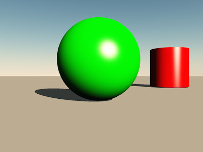
The main camera in my example will be simulating the right eye POV.

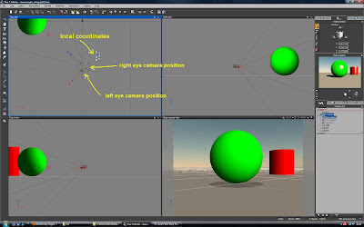
Now you have to move the camera 2 to the new position for the left eye POV.

Since the human eyes are positioned parallel to each other, just a certain distance apart, you want to move the camera 2 in a parallel movement away from the main camera.
The best way to do this, is to select camera 2 and at the appearing Gizmo choose "L" for using the "local coordinates" system. The camera 2 will slide in the X axes away from the main camera, just the way we need it to find a fitting left eye POV.


Like mentioned above, it depends on your scenery, objects and the scale of your scenery, to find a good distance between both cameras.
The eyes (cameras) distance is important, too, to control the strength and correctness of your 3D image effect.


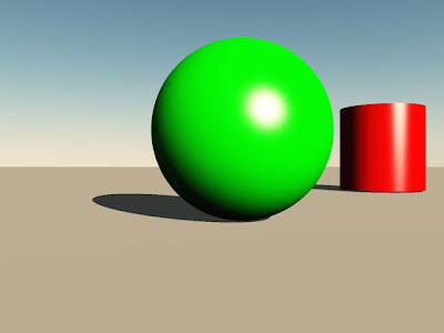
Left eye POV rendered:


Right eye POV rendered:


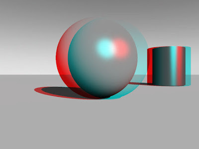
Here is the resulting image, combined in a free program called "StereoPhoto Maker" - using the "Anaglyph" mode with red/cyan colors:


Maybe i can find a calculable formula for the relation between eye distance and scenery scale - and i will add it to this little tutorial some day - but for now you'll have to go by trial and error to find a good eye distance - but it's not really too hard, to get quick results, IMHO.

Freitag, 14. August 2009

To "lock" a terrain or object to it's position and secure it from being moved, scaled or newly oriented ...

If you try to "lock" a terrain or object in a scene, so it won't be movable or changed in size or orientation by accident, there is a workaround setting possible - at least in Vue 7 Infinite - not sure, if there are all those options in smaller or older versions of Vue available.

You can use a function in the "Animation" tab in the top right corner - using it, you don't even have to use the normal build in layer lock function to be selected.

Say you have two terrains in your scene, but one is suppose to be locked from an accidental movement :

- add one simple primitive object, for instance a sphere to the scene and position it way far from all objects/terrains in the scene, doesn't matter left/right/up/down .... just that it's not to be seen and able to touch/select anymore - maybe call it "lock" for better recognition.
(But remember, you have to leave this "lock"-object in the main layer 1, otherwise you won't be able to select it in the "to link" list !)

- add a sphere (or any other simple object) being the "lock" and select the terrain/object that is suppose to be "locked" in position


- click on the "Animation" tab in the top right corner


- in the "link to" selection link this terrain to this sphere we named "lock"


- below this "link to" selection is a slider called "Response"


- move the slider to the total right, so you have a total "Loose" response selected


- that's basicly all there is to do


What happens now, if you accidently select this not to be moved terrain and wanting to move the XYZ-gizmo ?

You will get a warning window saying "You cannot change the relative position, size or orientation of objects that are connected using loose dynamics" and asking "Do you want to revert to "perfect" forward dynamics ?"


Here you click on "Cancel", since you want to keep it in this "Loose" dynamics setup and therefore it will stay always in position, 'cause it stops you from making any movements, size or orientation changes ... !

Logically you can add as many "lock" objects to your scenes as you want for more control - but basicaly just this one sphere is good enough to work as a "lock" for all following terrains/objects using the above described way.

Maybe this can be helpful to some of you, that don't like to work with the normal layer lock function ...

Dienstag, 26. Mai 2009

How to lock objects to a main object while keeping same distance - in Vue

Here as an example i use two spheres - one being the 'sun' the other a 'planet'.
The planet is suppose to be hooked to the sun, while keeping the same distance between them, even moving the sun or rotating the planet around the sun.


Following image shows the above described setting:


Here we go:

- choose the moon object/sphere
- then switch to the 'numeric' tab in the top right corner
- there are 5 buttons on the left side
- then select the fifth button called 'pivot position'
- here select the button next to the X-field called 'show pivot on/off'
- in the center of the moon object/sphere appears a green dot which is the pivot point of the moon
(following image shows the above steps taken)


- now go in Top View and adjust the view, that you can see the planet and sun together
- with the mouse move over this green pivot point, click and hold left mouse button and an arrow-cross will appear
- now move the pivot point to center of sun, a green line appears
- since you've moved the pivot point, the X-Y-Z-gizmo moves along
- now you only have to select the rotate symbol and from now on you can rotate the planet around sun keeping it always the same distance
(following image shows the above described steps)


For exact positioning of the pivot point copy the sun center X-Y-Z-coordinates to the pivot coordinates, but handpositioning should be accurate enough ...


Just to add - now after adjusting the pivot point, you can link the planet to the sun - so this complements your system.
(following image shows the mentioned link settings)


Now with the planet linked to the sun, you can move the sun, with the planet following along - still always being able to rotate the planet separate around the sun always keeping the exact orbital distance ...

Samstag, 9. Mai 2009

3D text - one way, how to curve it in Vue ...


Above is an example image, how it will look like after the "intelligent" or "normal" (with some angle tweaking by hand) dropping mode ...

Well - i don't know exactly, how you want your text positioned, the length of it, the angle or whatever, but sure you can use the text function of VUE and run a text in a curve.

You can use a cylinder, for example, but that's only one object, that can be used as the base shape of a curve.

Just produce your text - the letters in a word are grouped, but in the object list window to the right you can select each single letter one after each other.

Call up a cylinder object, rotate it 270 degrees - . Now you have the text hovering above the cylinder. The diameter of the cylinder has to be bigger than the length of the text/words.

Now select each single letter one after each other and use VUE's normal or intelligent object drop function - for sure you use this function a lot for other stuff - the lowest button on the left side vertical bar.

Then repeat this for each letter - just watch out, that there is just enough space between each letter, that they can't touch each other while dropping onto the cylinders perimeter.

If you look at the above example image - the green text was done by using the intelligent dropping with the right mouse button - the red text was done by using the normal dropping with the left mouse button. The red text was more work, because after normal dropping each letter is always standing vertical, doesn't matter the curved surface below. There i just selected each letter and just rotated each a bit to fit their angle to the cylinder curve.

Sure this can be done with easier functions in other 3D applications, but if you want to use the VUE text rightaway and don't want to start exporting-importing-exporting-importing stuff, this is a way to do it.

Freitag, 8. Mai 2009

A way to prepare and use DEM geological data files for use in Vue

This tutorial describes a method, to prepare DEM geological data files for use in Vue. Here we go :


Go to the website:
seamless.usgs.gov/

There you can call up a US and a few whole world maps (mostly North America terrain in detail), a program opens up in your browser (it takes a moment to load the data), where you can find places through different search options for example and use 'goto' at the bottom of the window from a list of found areas (There is a button 'Tutorial' for help).


You can use your mouse to draw a box around an area (be careful that you don't select an area too large in size - at least in the next windows appearing you can check the size of the file and re-adjust your selected area again) or you can enter coordinates, or template selection.


Then the 'Request Summary Page' appears telling you, what area you've grabbed, the size in MB and the download button for this area. But that's not what you want, yet.
You click on 'Modify Data Request' .


There you scroll all the way down to the bottom of the list and select 'GeoTIFF', where it says 'ArchGRID'. Then push 'Save Changes & Return to Summary' button.


It will return to the summary window - then push 'Download' - another window appears telling you the data will be prepared and at the end of the process you can download the zipped data.


What you get is a 'NED-.....' zip-file. Open it and extract the large *.tif image.


Now go to:
www.hangsim.com/3dem/
and download this '3DEM' converter program and install it. You can use this program from now on to convert the GeoTIFF images into DEM-files or other files to be used in Terragen for example - just read the info on this website. The program itself is pretty simple to use.


Starting the program a selection window appears, where 3DEM wants to know, what data you will be working with - click on 'GeoTIFF' and then load your GeoTIFF file.
The terrain will be displayed, in 2D or 3D (the square box area on the map will be calculated in 3D - you can move it around on the terrain-map) if you want.


Check the info regarding the height of the highest/lowest point and the size of the square area, because you might have to adjust the size in Vue by entering the right values in the X Y Z size input fields for this terrain, otherwise it probably will look stretched or squished
Now just save the terrain in DEM format (or what else you need), because this DEM-file can be loaded directly into Vue using the 'Files - Import Objects' option.

The rest is adjusting - sharpening or whatever you want to do with it ...

+++++++++++++++++++++++++++++++++++++++++++++++++++++

Just to make sure, your DEM file will look right in Vue ...

The info, that 3DEM gives - look at the image i've included


You can see the highest point in your terrain by calling up this color scale bar (to the left in the above image) - here in this area it's 4.19 km ( roughly 4190m, the exact values you get choosing 'Modify Scale' - where another window appears showing the colors regarding to the certain heights and the exact altitude range values). You need to adjust this in Vue lowest to hightest point in comparison with your ZERO water line (ground line for example), to get the terrain looking right in the Z-value.

What else you need to know is the X and Y length of your DEM terrain.
By displaying the 'DEM Specifications' window (in the menu with 'Show DEM Specs').
Here you'll get the Longitude and Latitude range.

The above image shows -110.961 to -110.385 longitude.
Subtract 110.385 from 110.961 and you get 0.576
Multiply 0.576 x 110 km (110km is roughly 1 degree of the circumference of the earth) and you'll get 63.36 km as length in X-value.
Same calculation for the Y-value.

These are the values you'll need as input in Vue for the terrain size. The above 63 km width might be way to large scaled to be used in Vue (RAM, handling and render time problems) !

So, for example, down scale the above calculated 63 km X-width by dividing it with 10 or even 100 - so you'll get like 6.3 km or 630 meters of terrain size - to large of an area in Vue will give you trouble with eco or whatever, since it has to cover an extreme large area with plants ...


Here is an example - Mount Moran next to Jackson Lake - Grand Teton in Wyoming ...
The quick calculated scene above and a real photo from the internet (through Google Earth photo links) in comparison between virtual and real landscape:


I might have to adjust the height just a little better - but it does work very good in my opinion.


Good luck with your DEM experiments ...

Working with 'Depth of Field' in Vue 6

By adjusting the values 'blur' and 'focus' you can control the two bars distance from each other - if the bars inclose your object, it will stay in focus.

Here are 3 example images:

Pic 1 - use an object as target - here 'Kugel2' (sphere2) - by selecting camera and choose the target, which should stay in focus (or use the focus-value method - look at pic 2 info below):


Pic 2 - adjust the focused area between the two bars with 'focus' and 'blur' settings.
By changing the 'blur' (in the image the german 'Unschärfe') value, you change the bars distance from each other, meaning the focus area size.
By changing the 'focus' value, you are moving the small focus box (which is connected to the camera symbol). This box you should move over your object in focus by changing this focus value (or by using the target method in pic1 above).
The focus box area between the two bars is moved back and forth with this focus value:


You can see in the rendered image in the main window, only the sphere with horizontal red bars, which is positioned in the focus-box bar area, is rendered clear. The front and back spheres are blurred.
If you want a more smoothed blurred depth of field render, you need to use the Hybrid v2.5 render method in the render options window - in the render quality settings - there is a edit-button next to 'depth of filed' setting.
Clicking this edit button - opens another window, where you can choose between raytraced or Hybrid v2.5 method - and you can adjust the number of render passes, to get even closer to your wanted quality.
Pic 3 - take a look at the rendered main window - setting was Hybrid v2.5 method with 3 render passes:


Still - with the used sun position in the above image, the shadow of the first sphere reaches from the blurred area below the front sphere into the focused area of the second sphere. If this is wanted or not, the artist has to decide ...